Purpose
The standard of care (SOC) for locally advanced cervical cancer (FIGO stage IB-IVA) consists of external beam radiotherapy (EBRT) to the pelvic area (e.g., 45 Gy in 25 fractions) with concurrent chemotherapy (e.g., 5 cycles of 40 mg/m2 cisplatin), followed by 4 fractions of high-dose-rate (HDR) brachytherapy (BT) (e.g., 28 Gy in 4 fractions), with an overall treatment time of 6-7 weeks [1]. In recent years, an increase in the use of intensity modulated radiation therapy (IMRT) or stereotactic body radiation therapy (SBRT) boost as a BT replacement has been associated with a negative impact on the survival of patients [2-5]. Han et al. reported a 12% better 4-year overall survival rate for patients receiving BT, showing that it is an essential component of SOC [2]. Since the late 1990s, MRI-based image-guided adaptive brachytherapy (MR-IGABT) has gradually replaced traditional BT planning based on 2D orthogonal X-ray imaging, allowing to move from dose prescribed to non-specific A points, to personalized dose distributions according to 3D dose volume histogram (DVH) parameters [6]. Since 2005, the Groupe Européen de Curiethérapie, the European Society for Radiotherapy and Oncology (GEC-ESTRO), and the International Commission on Radiation Units and Measurement (ICRU Report 89) developed comprehensive guidelines for MR-IGABT targets and OARs delineation as well as identifying DVH parameters for prescribing, recording, and reporting doses [7-9]. Since 2008, GEC-ESTRO GYN network sponsored by the Medical University of Vienna has launched both a prospective multicenter study (EMBRACE I closed in 2015 with 1,416 patients) and a retrospective study (RetroEMBRACE closed in 2013 with 852 patients) [10-12]. These studies determined that achieving a target dose of ≥ 85 Gy EQD2 to high risk clinical target volume (HR-CTV) D90 is associated with a 3-year local control > 96% in tumors ≤ 30 cc, and > 91% in tumors > 30 cc. Since 2016, there is an ongoing multicenter prospective study (EMBRACE II), where evidence-based planning aims (soft constraints) and dose limits (hard constraints) on target structures (gross tumor volume [GTV], HR-CTV, and intermediate risk clinical target volume [IR-CTV]) and organs at risk (OARs; bladder, small bowel, sigmoid colon, and rectum) are used as guidelines to optimize BT dose distributions [1, 13, 14].
Intra-cavitary (IC) brachytherapy applicators involve the combination of an intra-uterine tandem and an intra-vaginal component consisting of either ovoids (T&O), a ring (T&R), split rings (T&SR), or a cylinder (T&C). For FIGO stage IIIB-IVA patients with extensive parametrial and/or vaginal tumor extensions that cannot be covered adequately with IC-only BT, an important development was the addition of interstitial (IS) needles to further shape the dose asymmetrically, which has been shown to improve the therapeutic ratio [15, 16]. Earlier combined IC/IS techniques involved either trans-perineal or trans-vaginal free-hand implantation of metallic needles, which required considerable skills from the radiation oncologist to accurately reach the target [17]. This has led to the development of combined IC/IS applicators that use the IC vaginal component as a template to guide straight needles made of either metal or less invasive plastic.
Combined IC/IS applicators can be broadly categorized as Utrecht-style (T&O/IS) or Vienna-style (T&R/IS) [15, 18, 19]. Examples of commercially used Utrecht-style applicators include the Utrecht applicator and more recent Geneva applicator (Elekta, Stockholm, Sweden), and examples of Vienna-style applicators include the Vienna applicator and interstitial ring CT/MR applicator (Elekta, Stockholm, Sweden). The Vienna-II applicator modified the Vienna applicator, with an additional cap allowing the use of IS needle trajectories with an obliquity of 20° relative to the tandem [20]. The recently commercialized Venezia applicator (Elekta, Stockholm, Sweden) uses a set of intra-vaginal lunar ovoids (combining Utrecht- and Vienna-style), with an intra-vaginal template that alternates between straight and 20° oblique IS needle trajectories [21, 22]. IS needles are secured to the applicator using guiding tubes (GT), and an insertion tool can be used to accurately control needle depths making IC/IS techniques accessible to more practitioners. Combined IC/IS with the use of oblique needles has been reported to improve dose coverage in distal parametrial tissues relative to using straight needles only [23, 24]. A comprehensive review of brachytherapy applicators for cervical cancer was provided in a study from Mourya et al. [25].
Modern commercial combined IC/IS BT applicators are expensive and only available in a few specialized centers limiting its adoption. This has especially been a concern for low- and middle-income countries, particularly those in sub-Saharan Africa, where cervical cancer is still the leading cause of death in women [26].
A simple low-cost approach is to modify an existing IC-only applicator for combined IC/IS BT. Patel et al. drilled holes through the apex of a Miami multichannel cylinder (Elekta, Stockholm, Sweden) in order to use the six peripheral cylinder channels as templates for IS needles [27]. Petric et al. drilled holes to guide IS needles on home-made ring caps designed to attach on Varian T&R IC applicators [28]. Fredman et al. developed the Ellis caps in cast polyresin by modifying the 7.5 mm build-up caps of the CT/MR split ring applicator (BEBIG Medical GmbH, Berlin, Germany), with two rows of five equally spaced inner and outer holes to accommodate metallic straight needles [29].
3D-printing offers another low-cost approach to modify an existing IC-only applicator. Lindegaard et al. used a Vienna-style 3D-printed intra-vaginal template (without a ring channel) to combine a tandem with both straight and oblique needles [30]. Several authors reported using 3D-printing to produce intra-vaginal cylindrical templates for curved IS needles with or without the use of a central channel to accommodate a metallic fixation rod or an intra-uterine tandem [31-36]. Logar et al. modified a T&R IC applicator with a 3D-printed add-on, resulting in a Vienna-style IC/IS applicator with straight and oblique IS needles [37]. Similarly, Marar et al. modified a T&O IC applicator with a 3D-printed tandem anchored radially guiding interstitial template (TARGIT), resulting in a Utrecht-style IC/IS applicator with straight and oblique IS needles [38].
The increasing availability of desktop 3D-printers (as opposed to outsourcing industrial 3D-printers) has made it possible to develop clinical workflows to produce low-cost patient-specific combined IC/IS applicators [39]. The most common technologies include fused deposition modeling (FDM) with a thermoplastic material (e.g., PLA, PETG, and ABS) or stereolithography (SLA) with a photo-resin material. Several authors reported workflows involving scanning a patient with a packing material in the vaginal vault, and then 3D-printing a patient-specific vaginal vault IS template for BT with or without combination with an intra-uterine tandem [40-48].
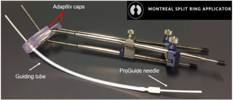
Adaptiiv Medical Technologies Inc. (Halifax, Canada) has recently developed 3D Brachy, a software that allows users to create personalized 3D-printed BT applicators without requiring any skills in CAD modelling. This software currently involves modules for plesiotherapy (surface applicator) and combined IC/IS BT using vaginal vault templates (Halifax vault applicator) [45, 49]. This work is part of an ongoing collaboration between Adaptiiv Medical Technologies Inc. and CHUM Hospital (Montreal, Canada) to develop the Montreal split ring (MSR) software module for 3D Brachy [50-52]. The MSR software module allows users to re-design the original build-up caps of the CT/MR split ring applicator (BEBIG Medical GmbH, Berlin, Germany) with relatively inexpensive SLA 3D-printing technology to allow attachment of the guiding tubes used by the Venezia applicator to secure ProGuide plastic needles (Elekta, Stockholm, Sweden). The resulting 3D-printed Adaptiiv caps have IS needle trajectories with obliquity based on a patient-specific pre-plan that can be tailored to each treatment according to EMBRACE II planning aims. Figure 1 shows an assembled prototype of the Montreal split ring applicator. The purpose of this work was to present an end-to-end (E2E) validation of the workflow used to produce the MSR applicator.
Material and methods
The workflow needed to produce the Montreal split ring applicator involved three steps: 1) Caps design pre-plan done with a brachytherapy TPS; 2) Caps design using 3D Brachy; and 3) Caps production using an SLA 3D-printer.
Required components for the MSR applicator
The first component of the MSR applicator consisted of the CT/MR split ring applicator (BEBIG Medical GmbH, Berlin, Germany) [53]. This applicator combines an intra-uterine tandem with a pair of left and right split ring channels, allowing an easier insertion compared with a closed ring applicator, and is highly customizable permitting to separate the split rings symmetrically or asymmetrically in 5 mm increments, yielding 6 possible diameters between 38 and 68 mm. The applicator can be stabilized without intra-vaginal lateral packing (only inferior) by separating the split rings to the maximal lateral distance that can be tolerated by the patient. Reusable build-up caps that work as sleeves around each split ring channel create additional spacing with a radiation source. Different sizes of build-up caps are available with different combination of thicknesses and widths between 5, 7.5, and 10 mm. The applicator is made of a durable titanium alloy that is CT-compatible and MR-conditional (using SAR limited sequences).
The second component of the MSR applicator involved ProGuide needles system (Elekta, Stockholm, Sweden). Disposable ProGuide needles are made of a high quality plastic, and come with either sharp or rounded tips. A flexible tungsten alloy obturator is inserted inside the needle to achieve the needle rigidity needed for implantation. Disposable guiding tubes are inserted in specific slots of the Venezia applicator’s lunar ovoids [21]. Guiding tubes are secured to the applicator when the tips of IS needles reach the ends of guiding tubes, and enter lunar ovoids’ needle tunnels. After the lunar ovoids and guiding tubes are assembled, an insertion tool is used to control needle depths up to 5 cm. The needles are then secured to the guiding tubes with a plastic nut at the bottom end of guiding tubes. For CT imaging, radio-opaque CT markers indicate the position of the most distant source dwell position.
CAD modeling for 3D Brachy
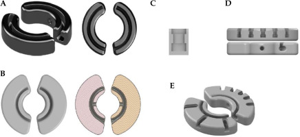
Figure 2 shows different CAD models that were developed to design Adaptiiv caps with 3D Brachy. Fusion 360TM (Autodesk Inc., California, USA) was applied to reproduce the original black (5 × 5 mm2) build-up caps (10 mm width) of the CT/MR split ring applicator, as shown in Figure 2A. These caps include both a thread compatible with the fixation screw included in the CT/MR split ring kit (based on a 6-32 UNC 2B ANSI standard thread) and a central canal for the titanium split rings (channels). The 5 mm outer section of the original caps (exterior to the split ring canal) was then made wider by 10 mm (20 mm total width), as shown in Figure 2B, and integrated in 3D Brachy. Fusion 360TM was also used to reproduce the guiding tube slots found on the Venezia applicator’s lunar ovoids (Figure 2C), which were then integrated into 3D Brachy. Figure 2D and 2E show an example of patient-specific Adaptiiv caps produced by 3D Brachy that combine both widened caps and guiding tube slots based on IS needle trajectories defined in a caps design pre-plan.
Creation of IS needle trajectories
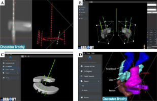
In this work, Oncentra Brachy (Elekta, Stockholm, Sweden) was used to create a caps design pre-plan, which consisted of two components (Figure 3A). The first component involved a manual reconstruction of the split ring channels over a length of ~35 mm. The second component required manually reconstructing IS needle virtual trajectories based on a visualization of important target structures. These virtual trajectories should extend at least ±1 cm from the split ring channels in the superior/inferior direction and intersect important target structures. Dummy dwell positions were then activated every 5 mm to complete the caps design pre-plan, which was imported into 3D Brachy as a DICOM-RT Plan file.
MSR software module (caps design)
For visualization, the MSR software module can import alongside the DICOM-RT Plan file (caps design pre-plan) both DICOM-RT structure set (RTSS) files and DICOM images (CT or MRI). Following importation of the caps design pre-plan, the right and left split ring channels were selected, and an automatic co-registration was done to position the widened caps CAD models on the reconstructed split ring channels, as shown in Figure 3B. Rotation and translation tools are available to fine-tune the co-registration manually as needed. This allowed 3D Brachy to position the virtual IS needle trajectories relative to the widened caps CAD models and subtract both guiding tube slots and IS needle tunnels with an angulation corresponding to the planned IS needle trajectories (Figure 3C). The resulting Adaptiiv caps CAD models can be exported as both RTSS files (for visualization back in the BT TPS) and STL file (for 3D-printing), as displayed in Figure 3D. CloudCompare, a 3D point cloud and triangular mesh processing software, was used to compare surface distances of Adaptiiv caps between the STL and RTSS files generated by 3D Brachy [54]. For this analysis, the RTSS structure was converted to an STL model using 3D slicer [55]. Various spatial features were then compared between the software files and 3D-printed prototypes.
Production of Adaptiiv caps
In this work, the STL files were sliced for 3D-printing on a Form 3 SLA 3D-printer using PreForm (Formlabs Inc., Massachusetts, USA). Adaptiiv caps prototypes were produced with both BioMed Amber (ISO 10993 biocompatibility and 50 μm layer height) and BioMed Clear (ISO 10993/USP class VI biocompatibility and 100 μm layer height) photo-resins (Formlabs Inc., Massachusetts, USA). Prototypes were 3D-printed both flat to the surface without any support and with an angle (along either the short or long axis of the caps) relative to the built platform using support. For all caps, internal support was deactivated in PreForm. For caps 3D-printed with an angle, touch point size was reduced to 0.4 mm to simplify removal from the built platform. Moreover, PreForm automatic support generation was applied only to the superior flat surface of the caps, and modified to remove all points of contact close to IS needle holes, guiding tube slots, and split ring canal entrances. 3D-printed caps were cleaned by immersion in 99% isopropyl alcohol for 20 minutes (Form Wash, Formlabs), and then allowed to air-dry for at least 30 minutes. For BioMed Clear resin, cleaned caps were cured for 60 minutes at 60°C, and for BioMed Amber resin, cleaned caps were cured for 30 minutes at 70°C. Post-processing was then needed to break the support rods with pliers and a razor blade, the caps were polished with 180 and 400 grit sanding sponge and sandpaper, and dust was removed with compressed air to get a smooth finish. Afterwards, Adaptiiv caps were steam-sterilized in an autoclave at 132°C for 4 minutes using a pre-vacuum cycle, followed by a 25 minutes dry phase. Prototypes were tested for their functionality both pre- and post-sterilization.
End-to-end validation
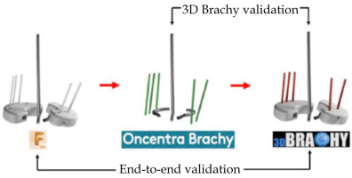
To validate the design accuracy of IS needle trajectories generated with the MSR applicator production workflow, a pair of ground truth Adaptiiv caps was selected to be replicated with a total of five IS needle trajectories. The left cap had two IS needle trajectories (N1, N2), and the right cap had three IS needle trajectories (N3, N4, N5) (Figure S1 of Supplementary Material). After 3D-printing of the ground truth caps, the Montreal split ring was assembled and CT-scanned in air with radio-opaque markers inside the five IS ProGuide needles. A caps design pre-plan was subsequently made in Oncentra Brachy to manually reconstruct identical IS needle trajectories based on the radio-opaque markers. Finally, 3D Brachy was used to produce CAD models of the replicated caps. For analysis, registrations of ground truth caps, reconstructed split ring channels from the TPS pre-plan, and replicated caps were made in Fusion 360TM with spatial errors < 50 μm. IS needle trajectories of both ground truth and replicated caps were modeled as rods by extrapolating IS needle tunnels, and a coordinate system was defined at each needle positions with the z-axis parallel to the intra-uterine tandem, the x-axis parallel to the caps’ short axis, and the y-axis parallel to the caps’ long axis. Spatial (x, y, z) coordinates of intersection points between the centroids of each IS needle trajectories and planes defined at the level of the cervix (z = 0 cm) and a clinically representative needle depth of z = 3 cm were applied to evaluate spatial deviations between replicated, TPS pre-plan, and ground truth IS needle trajectories as distance-to-agreement (DTA) and angular deviations in IS needle trajectory pitch (y, z) and yaw (x, z) angles. In this work, angular deviations in roll (x, y) were excluded from the analysis given that rotations of the IS needle trajectory around its axis have no dosimetric impact, and any remaining deviations (relative to the z-axis) can be accounted by a combination of pitch (y, z) and yaw (x, z) angular deviations. Figure 4 presents the entire E2E workflow validation (replicated vs. ground truth) as well as the 3D Brachy software workflow validation (replicated vs. TPS pre-plan).
Results
Validation of 3D Brachy software files
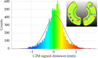
Table 1 shows measurements of various spatial features between software files and 3D-printed prototypes both pre- and post-sterilization. IS needle inner tunnel diameters and guiding tube slots (bottom and top sections) of RTSS, STL, and 3D-printed prototypes (BioMed Clear and BioMed Amber) agree within ±0.1 mm and ±0.2 mm, respectively. A similar comparison between Adaptiiv caps’ widths and thicknesses agree within ±0.1 mm and ±0.7 mm, respectively. Figure 5 shows morphological differences calculated between surfaces of DICOM-RT structure set (RTSS) and STL models of the same Adaptiiv caps generated by 3D Brachy. This analysis was done with CloudCompare software by converting the STL derived from the RTSS structure set as a cloud of points (reference cloud) and calculating signed cloud-to-mesh (C2M) distances with the STL surface generated by 3D Brachy (compared mesh). A Gaussian fit shows that morphological differences are ≤ 1.3 mm (μ = 0.08 and σ = 0.4 mm). 3D-printed prototypes were also CT-scanned at 120 kVp to evaluate HU numbers and their corresponding mass density values, as presented in Table 2.
Table 1
Comparison of spatial dimensions (mm) between 3D Brachy software files (DICOM RTSS and STL) and 3D-printed prototypes measured with a digital caliper (n = 10)
Validation of caps prototypes
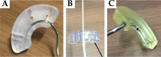
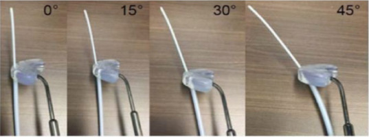
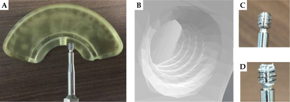
Based on prototype testing, a 3D-printing angle of 10° relative to the built platform, either along the short or long axes of the caps with some post-processing, is found to yield the most reliable results. In particular, BioMed Amber prototypes 3D-printed at 0° can sometimes get slightly chipped during removal from the built platform, while the bottom layer of BioMed Clear prototypes 3D-printed at 0° can sometimes delaminate (peel off) following sterilization (Figure S2 of Supplementary Material). Figure 6 shows different properties that are successfully confirmed to be functional both pre- and post-sterilization for both BioMed Amber and BioMed Clear prototypes. In particular, titanium split rings can glide smoothly in the 3D-printed canals, IS guiding tubes with obliquity angles of 0°, 15°, 30°, and 45° (along with ProGuide needles and obturators) can securely attach to 3D-printed slots (Figure 7), and the caps can be properly fixed to the split rings using the original CT/MR split ring fixation screw. Fixation screw threads (and their orientations) are the most sensitive feature of the 3D-printed caps. A minimum mesh resolution of 0.1 mm in 3D Brachy (Figure 8B) was found to be necessary for proper screw fixation using BioMed Clear caps prototypes 3D-printed with a layer height of 100 μm. Using these settings, the number of times the screw could be re-used before stripping the threads was found to exceed 10 times for both BioMed Amber and BioMed Clear prototypes. For the BioMed Clear prototypes, the screw can create a small amount of debris (Figure 8D), which can easily be cleaned with sterilized water at the time of implant.
E2E accuracy of the design workflow
For the validation of the workflow for Adaptiiv caps production, Figure S3 of Supplementary Material shows the comparison between IS needle trajectories of replicated caps (red) and TPS pre-plan (green) as well as the E2E comparison between IS needle trajectories of replicated caps (red) and ground truth caps (white) using the methodology of Figure 4. Spatial deviations between the intersection coordinates of the IS needle trajectories with the plane of the cervix (z = 0 cm) and the plane at a clinical needle depth of 3 cm are shown in Table 3. Similarly, angular deviations in pitch (Δθpitch) and yaw angles (Δθyaw) are presented in Table 4.
Table 3
Spatial deviations as distance-to-agreement (DTA) (mm) at the level of the cervix (z = 0 cm) and a 3 cm needle depth
Table 4
Deviations in pitch (y, z) and yaw (x, z) angles from the tandem
Discussion
Comparison with other IC/IS applicators
In this work, TPS pre-plans were made with Oncentra Brachy, but other HDR treatment planning systems, such as BrachyVision (Varian Medical Systems, Palo Alto, California, USA) or SagiPlan (BEBIG Medical GmbH, Berlin, Germany) could be used to produce the caps design pre-plans required by 3D Brachy. Based on the prototyping results, the recommended maximum number of IS needle trajectories per cap to be virtually reconstructed in a TPS pre-plan is 5 (although up to 7 is technically feasible), and IS needle trajectory angles are recommended to be kept between 0° and 45° relative to the tandem. A current limitation of the MSR software module is that 3D Brachy is not able to modify imported IS needle trajectories, so the user has to go back to the BT TPS if any modifications are needed. One of the main advantages of using a 3D-printed workflow is the ability to produce cap templates with patient-specific IS needle trajectories. Fredman et al. reported that in some cases, the target structures could not be reached using the generic straight IS needle trajectories of the Ellis caps, and free-hand needles affixed to the tandem were required [29]. The Adaptiiv caps are significantly more versatile, since IS needle trajectories with their complex combinations of lateral and anterior/posterior angles are possible as long as they intersect the outer section of the caps. Although this work is based on the Venezia ProGuide IS needle system, 3D Brachy also allows the user to make Adaptiiv caps without guiding tube slots using user-defined tunnel diameters, which could be compatible with other needle systems. Moreover, the Venezia applicator’s template of alternating straight and 20° oblique IS needle trajectories has the limitation of being generic. For example, the lateral most positions are oblique on the 22 mm lunar ovoids, but straight on the 26 mm and 30 mm ovoids. A consequence is that, for larger lunar ovoids, the closest 4 oblique IS needle trajectories have to be selected (instead of 2) to properly cover distal lateral parametrial tumor extensions. The 3D-printed Adaptiiv caps have the potential to reduce the number of required IS needles making the implant procedure both less costly and less invasive, particularly for patients with low platelet count, who are at risk of heavy bleeding. Moreover, since the Adaptiiv caps are unique, there is a reduced risk of clinical incidents, where guiding tubes are secured either to the wrong slots, leading to sub-optimal needle configurations, or mixed up, leading to the wrong dwell times being delivered. The MSR intra-uterine tandems also have a wider range in length (2-8 cm vs. 3-7 cm for the Venezia), and its titanium composition is less likely to break.
A significant limitation of the Adaptiiv caps developed in this work is the rather large size of the widened caps, meaning that the smallest outer diameter is 6.7 cm instead of 4.7 cm for the original (5 × 5 mm2) build-up caps. For comparison, the Venezia applicator’s lunar ovoids have an outer diameter of 3.4 cm to 4.2 cm. It is therefore expected that only patients with above average vaginal vault sizes could accommodate current versions of Adaptiiv caps. Further work will be needed to adapt the CAD models for smaller anatomies, which could be done, for example, by making the caps thicker and positioning the guiding tube slots under the split ring canals. Another potential benefit of making the caps thicker is the possibility of using the caps to treat inferior vaginal tumor extensions, thus, serving a similar function as the vaginal caps of the Venezia applicator (which cannot be used with oblique IS needle trajectories) [23]. Alternatively, for smaller vaginal vault sizes, BEBIG Medical GmbH (Berlin, Germany) is currently developing the Tulip applicator family, which consists of 3D-printed add-on kits for some of their intra-cavitary applicators, including Henschke (very small size), ring (small size), and Fletcher (mid-size). Users have a choice of four generic needle template patterns, such as compact, standard, oblique extended, and lower extended [25]. Another option for patients with smaller anatomies is Adaptiiv Medical Technologies’ Halifax vault applicator without intra-vaginal channels [45].
Material selection and cost evaluation
During a combined IC/IS BT treatment, Adaptiiv caps will come in contact with both the vaginal and cervical mucosae as well as blood. Therefore, the 3D-printing material selected should have a high level of biocompatibility and be sterilizable using a compatible method. Oth et al. mentioned that popular low-cost FDM thermoplastics, such as PLA and PETG, suffer from morphological deformations following steam sterilization techniques above 121°C [56]. However, it is still possible to use FDM thermoplastics, if a low temperature sterilization technique, such as ethylene oxide (EtO) or vaporized hydrogen peroxide (VHP), is available [33, 39, 57]. PC-ISO (USP class VI and ISO 10993; Stratasys, Rehevot, Israel) is an example of biocompatible polycarbonate thermoplastic that has been used as material for 3D-printed GYN applicators [31, 43, 58]. On the other hand, SLA photo-resins are a good option for single-use high temperature steam sterilization. Accura® ClearVue™ (USP class VI; 3D Systems, South Carolina, USA) and both Dental LT and Dental SG (ISO 10993) (Formlabs, Massachusetts, USA) have been utilized as material for 3D-printed GYN applicators [41, 48, 59, 60]. PEEK is a high temperature thermoplastic material available for FDM 3D-printing, and is appropriate for high temperature steam sterilization [35]. Kudla et al. had their patient-specific cylindrical template (PSCT) made of PEEK material validated by an independent contract testing laboratory for a sterility assurance level (SAL) of 10-6 using a biological indicator overkill method [35]. Finally, the design of 3D-printed BT applicators should be free of sharp edges and easy to clean.
In this work, Adaptiiv caps prototypes in both BioMed Amber and BioMed Clear SLA resins were produced with ≤ 0.2 mm accuracy with respect to their software files. Overall, Table 1 shows a slight expansion of the material following 3D-printing, which could be caused by a combination of uncertainties related to the 3D- printer’s laser spot size (85 μm), XY resolution (25 μm), and layer height (50-100 μm) for samples 3D-printed at 10°. Post-sterilization measurements do not seem to be affected by the resin’s thermal alterations, as they agree with pre-sterilization values within ≤ 0.1 mm [61]. In comparison, Sharma et al. reported an increase in outer dimensions and a decrease in inner dimensions of SLA 3D-printed surgical guides following steam sterilization [62]. Table 2 summarizes material properties of Adaptiiv caps. In particular, the heat deflection temperature (HDT), a measure of a polymer’s resistance to alterations under a given load at high temperature, is lower for these resins than the 132°C temperature used for sterilization. Therefore, it is unclear how many sterilizations procedure these caps could sustain without showing significant morphological alterations. Nonetheless, Adaptiiv caps prototypes in both BioMed Amber and BioMed Clear have been verified to be functional after a single sterilization procedure, and can henceforth be used as disposable devices. These caps also show near water equivalency on CT images making them suitable for TG-43 dose calculations. Formlabs recently released three new ISO 10993 and USP class VI SLA resins (i.e., BioMed White, BioMed Black, and BioMed Durable), which are likely to show similar results as the ones used in the current work [61]. For cost evaluation, a pair of Adaptiiv caps cost < 10$ USD in resin to produce with a 3D-printing time of less than 4 hours. Other expenses include the cost of a 3D-printer (~6,300$ USD for a form 3B+ SLA printer), the cost of equipment and materials for post-processing, a budget for the maintenance of a 3D-printer as well as staff needed to operate a 3D-printer and sterilize the caps. In comparison, Marar et al. reported that their TARGIT IS needle template costed ~5$ USD to produce in-house, with a turnaround time of 1-2 days, and ~100$ USD to outsource from a third-party vendor, with a turnaround time of 1 week [38].
Accuracy of the MSR design workflow
A comparison using five IS needle trajectories for caps that were replicated from a pair of selected ground truth caps and TPS pre-plan IS needle trajectories shows that 3D Brachy does not introduce any significant uncertainties that would impact the caps design process, with errors ≤ 1 mm (DTA) and ≤ 1° (Δθpitch and Δθyaw) at a needle depth of 3 cm. On the other hand, a full E2E comparison of the five IS needle trajectories for replicated caps and ground truth caps shows that the overall design workflow introduces rather large DTA errors of 3.3 ±2.1 mm and 7.3 ±2.0 mm at the cervix and at a needle depth of 3 cm as well as Δθpitch and Δθyaw values of 2.9° ±2.3° and 7.0° ±7.0°, respectively. In particular, Δθyaw values between IS needle trajectories on the left cap are 13.6° ±7.2°, while they are smaller for the right cap with 2.6° ±0.6°, suggesting that some of the left cap’s IS needles might have been slightly kinked during implant. There are multiple sources that can contribute to these uncertainties including CT-scan resolution (limited by a 3 mm slice thickness), visualization of radio-opaque CT markers, and implant reproducibility. In the current work, the results are not affected by curvature of the plastic needles in tissues, since our applicator was assembled and CT-scanned in air. However, in a clinical setting, the resistance of interstitial tissues to the flexible metallic obturators can create additional needle curvatures, which would affect implant reproducibility.
Fokdal et al. reported that IS needles virtually planned on pre-BT MRI scans could be reproducibly delivered (257 IS needles in 24 patients) at subsequent BT fractions for a tandem and ring template applicator [63]. Petric et al. reported in a prospective study (55 IS needles in 18 patients) that median differences in needle depth and radial angle (at the proximal end) between virtually planned pre-BT IS needle trajectories and implanted ones were 2 mm (range, 0-10 mm) and 4° (range, 0-30°), respectively [28, 64]. Tambas et al. showed in a prospective study (266 IS needles in 24 patients) that shifts in needle positions between virtually planned and delivered IS needle trajectories were frequent (68%). They reported a mean shift (at the proximal end) of 2.0 ±2.3 mm (range, 0-10 mm) between virtually planned IS needles from a CT-scan taken before insertion and delivered IS needles from a CT-scan taken after insertion [65]. These deviations are similar to the ones that we report at the plane of the cervix (proximal end). Moreover, it should be noted that the specific design of a needle template also has an impact on the accuracy of IS needle trajectories. Additional work will be needed to improve the design of Adaptiiv caps to be more robust to implant uncertainties. For example, increasing the cap’s thickness might help to stabilize the needles. Finally, it should be noted that the validation workflow developed in this work could be repeated using the same ground truth caps to evaluate random errors, or applied multiple times on the replicated caps (making replicas of replicas) to study a systematic drift in design accuracy.
Proposed clinical workflow
Figure S4 in Supplementary Material shows a clinical workflow proposal for the Montreal split ring that integrates the 3D-printing steps developed in this work to a traditional brachytherapy workflow. The first fraction could be delivered with customizable generic caps having IS needle positions and depths selected on a pre-BT MRI, which could be done using solid caps (Figure 2B) and inferior vaginal packing, but without an intra-uterine tandem (which would require anesthesia). STL files of these generic caps CAD models can be provided upon request by Adaptiiv Medical Technologies Inc., but a feature to customize these caps will be added to 3D Brachy in the near future. Alternatively, patient-specific Adaptiiv caps could be used at the first fraction, if a virtual TPS pre-plan is done based on a HR-CTV delineated on a pre-BT MRI that includes an intra-uterine tandem. General anesthesia and para-cervical anesthesia (PCA) were applied in studies by Fokdal et al. and Petric et al., respectively, to virtually pre-plan IS needles on a pre-BT MRI with reproducible results [63, 64]. For fractions 2 to 4, Adaptiiv caps can be produced based either on the HR-CTV delineated on the first fraction MRI to get 4 identical patient-specific caps, or if available, based on the HR-CTV delineated from a previous fraction MRI to obtain 4 distinct fraction-adapted caps (e.g., based on shrinkage of the target structures during treatment).
In this work, IS needle trajectories were reconstructed manually based on visualization of target structures. Sekii et al. developed a workflow to inversely design cylindrical templates with patient-specific IS needle trajectories designed to intersect a simplified polygonal representation of a vaginal tumor [32]. Other groups developed similar workflows to select IS needle trajectories for vaginal vault templates based on vaginal packing with MRI contrast-soaked gauzes [47, 48]. Kudla et al. automated the design of their PSCT applicator with Eclipse Scripting API using a TPS pre-plan based on a library of virtual straight and curved needle trajectories [35]. Eventually, optimal IS needle trajectories for Adaptiiv caps could be determined automatically without requiring a TPS pre-plan with an inverse optimization technique applied on the target structures. Garg et al. developed an algorithm to compute curvature-constrained channels for vaginal vault IS templates based on rapidly exploring random trees (RRT) [40]. Sohn et al. developed a mathematical model to optimize shielding thicknesses for IC cylinders with 3D-printed patient-specific tungsten shields [66].
In many cases, it is likely that most of the dosimetric gains of combined IC/IS BT come from a few well-placed needles (quality over quantity). The Adaptiiv caps have the potential to reduce the cost and make the implant procedure less invasive for patients by eliminating the use of superfluous generic IS needles.
Conclusions
In the current work, affordable SLA 3D-printing technology was successfully used to produce the Montreal split ring (MSR) applicator suitable for combined IC/IS brachytherapy. Prototypes 3D-printed with both BioMed Amber and BioMed Clear biocompatible SLA resins were verified to be functional both pre- and post-sterilization for IS needles with obliquity angles ≤ 45°. A dedicated software module in 3D Brachy was developed and validated allowing users to design patient-specific Adaptiiv caps without knowledge of CAD modeling. IS needle trajectories can be adapted over the course of the treatment based on frequency of MRI imaging, allowing to achieve a level of plan adaptability and conformity with EMBRACE II planning aims and dose limits not possible with generic combined IC/IS applicators. Moreover, this work presents an end-to-end (E2E) validation of the entire workflow used to produce the MSR applicator. A comparison between replicated and TPS pre-plan trajectories shows spatial deviations ≤ 1 mm (DTA) at a needle depth of 3 cm and angular deviations ≤ 1° (Δθpitch and Δθyaw), confirming a high level of fidelity between the 3D-printed prototypes and what was intended to be designed using 3D Brachy. In general, the E2E workflow presented can also be used to validate software developed to design any 3D-printed radiotherapy devices. The MSR applicator can be utilized with Elekta, Varian, and BEBIG Medical GmbH afterloaders using connections compatible with their respective transfer tubes, making combined IC/IS BT more accessible for low- and middle-income countries.


